
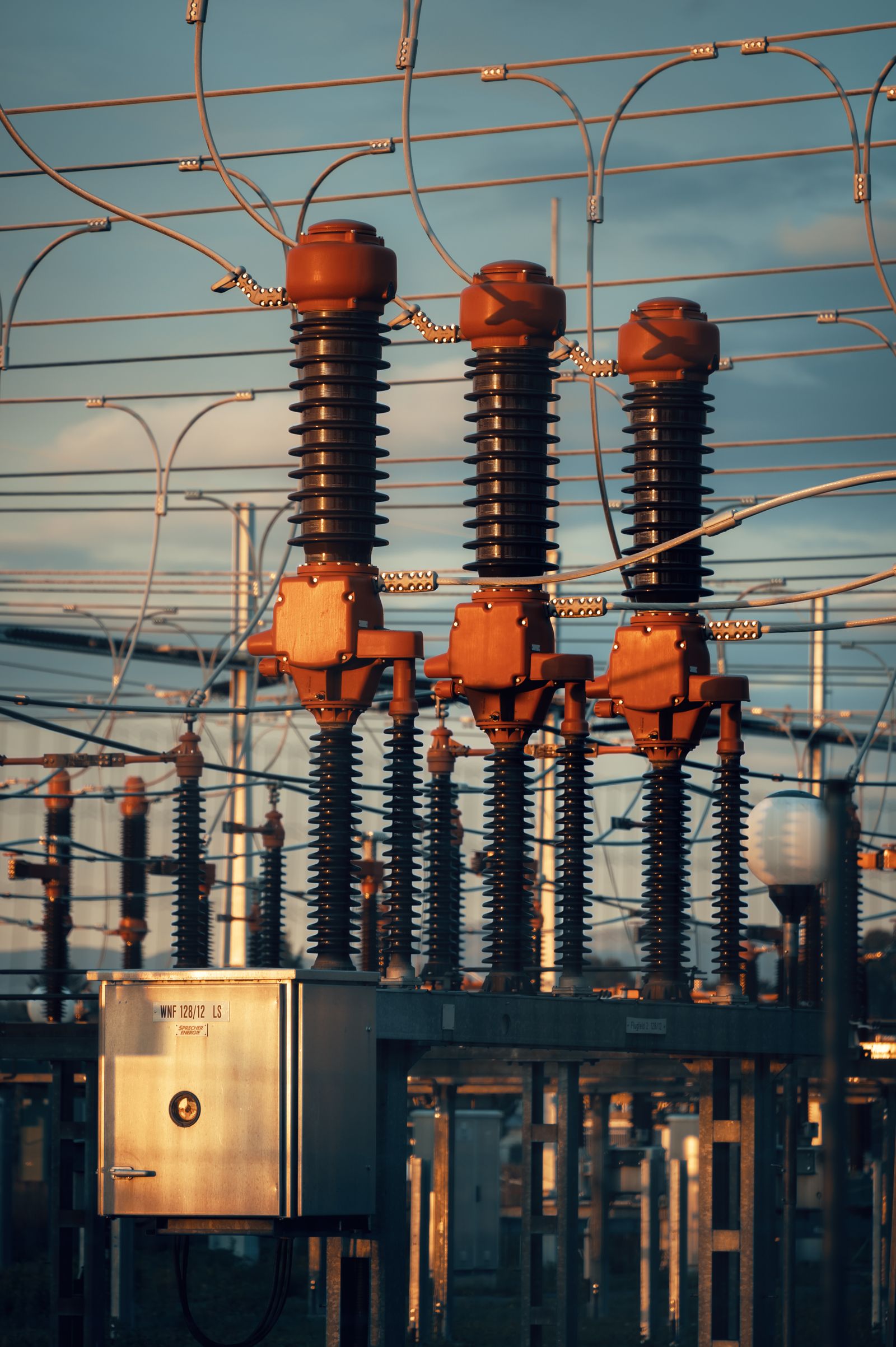
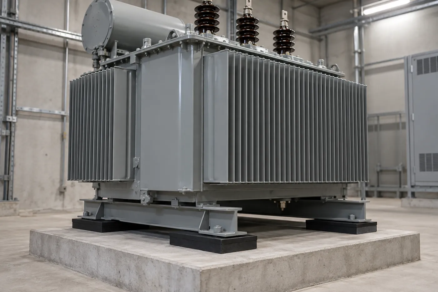
Transformer Anti-Vibration Pads & Vibration Isolation
Made-to-measure anti-vibration mats against transformer hum, structure-borne noise and building vibration – for substations, secondary substations and buildings.
✓ Engineered selection
based on your machine data
✓ Cut to size
mats, strips, pads & multi-layer systems
✓ Fast quotes
short-notice production & express possible
✓ Industry & research
we also supply leading universities & institutes
What natural frequency does your mounting need? → Try the free vibration isolation calculator
Why transformers should be isolated
Magnetostriction in the core makes transformers produce a characteristic hum at twice the mains frequency (100 Hz on 50 Hz networks) and its harmonics. This vibration is transmitted through the foundation as structure-borne noise into floors, walls and adjoining rooms. In buildings, in secondary substations in residential areas or in data centres, this quickly leads to complaints – and the building elements are subjected to higher stress over the long term.
Less hum
The resilient mounting interrupts the structure-borne noise path between transformer and foundation and reduces noise transmission into adjoining rooms.
Protecting the building fabric
Isolated foundations are subjected to lower dynamic loads. This helps prevent cracks, loosened connections and material fatigue.
Made to fit
Format, thickness and hardness are matched to the weight and support area of your transformer – including heavy power transformers.
Typical applications
Our anti-vibration mats and pads are used under transformers and electrical plant, for example in:
- Substations and secondary substations
- Compact and local distribution substations in residential areas
- Transformer rooms in buildings, hospitals and office complexes
- Data centres and industrial incoming supplies
- Cast-resin and oil-filled transformers
- Reactors, inverters and power converter installations
Our solution: resilient mounting made to measure
Depending on load, frequency and environment, we combine the right elastomer with the right thickness and geometry. For high loads, we supply heavy-duty mats up to 50 mm thick as well as multi-layer systems.
- Elastomer and PU mats for high static loads
- NBR where there is contact with transformer oil
- EPDM for outdoor installations exposed to weather, ozone and UV
- Cut as a full-surface mat, strips or individual pads
Recommended systems & technical data
With transformers, high loads are concentrated on small support areas (undercarriage, rollers, bearing strips). At the same time, the main excitation at 100 Hz (on 50 Hz networks) is relatively high – even a mounting with a natural frequency of approx. 15 Hz theoretically achieves over 95 % isolation efficiency.
| Recommended system | Load range (static continuous load) | Suitable for |
|---|---|---|
| Rubber granulate/fibre mat, class G6 – G8 | 0.30 – 1.50 N/mm² | Distribution and power transformers, bearing strips under the undercarriage |
| PUR elastomer, heavy | 0.60 – 2.5 N/mm² | very high point loads, low tuning, transformer rooms in buildings |
| Elastomer pads (NBR) | as designed | Oil-filled transformers with possible oil contact |
- For oil-filled transformers, make sure the materials are oil-resistant
- Make cable and busbar connections flexible to avoid acoustic bridges
- Check alignment and connections after initial settlement (first few days under load)
→ All load classes: Materials & technical data · Check your own values: Isolation calculator
Relevant datasheets (PDF, German): Rubber granulate mats G1–G8 · PUR elastomers
Mounting under rollers, undercarriages and support rails
Many transformers stand on rollers, an undercarriage or support rails, so the weight is concentrated on a few small areas. For the design, it is therefore not just the total weight that counts, but the geometry of the support points.
- Record the support geometry: number, length and width of the rollers or rails and their spacing.
- Plan load distribution plates: under rollers or narrow rails, steel plates spread the load evenly over the elastomer – keeping the bearing pressure within the permissible range.
- Prevent slipping: lock the rollers or provide lateral stops, without creating rigid connections to the foundation.
- Allow for oil contact: for oil-filled transformers, use oil-resistant materials or protect the bearing from leaks.
- Plan the installation: the transformer is briefly lifted to insert the bearings; check installation height and access beforehand.
- Make connections flexible: connect cables, busbars and cooling pipes flexibly so that no acoustic bridges are created.
Worked example: distribution transformer on elastomer pads
Simplified example, guide values only – the binding design is always project-specific. The example shows how load class, natural frequency and isolation efficiency are related.
| Quantity | Assumption / calculation | Result |
|---|---|---|
| Transformer | Operating weight 3,000 kg, 4 support points on the undercarriage, one 100 × 100 mm pad each under a load distribution plate | Support area 4 × 10,000 mm² = 40,000 mm² |
| Bearing pressure | 3,000 kg × 9.81 / 40,000 mm² | ≈ 0.74 N/mm² → rubber granulate class G7 (up to 0.80 N/mm²) |
| Natural frequency of the mounting (assumed) | Guide value for rubber granulate: from approx. 10–15 Hz, assumed conservatively here | f0 ≈ 15 Hz |
| Excitation frequency | twice the mains frequency on a 50 Hz network | 100 Hz |
| Frequency ratio | η = 100 Hz / 15 Hz | ≈ 6.7 (well above √2 → isolation range) |
| Isolation efficiency | 1 − 1/(η² − 1) = 1 − 1/(6.7² − 1) | ≈ 97.7 % or ≈ 33 dB |
Harmonics and 60 Hz networks – same mounting (f0 ≈ 15 Hz), different excitation frequencies:
| Excitation frequency | Frequency ratio η | Isolation efficiency | Level reduction |
|---|---|---|---|
| 100 Hz (fundamental, 50 Hz network) | ≈ 6.7 | ≈ 97.7 % | ≈ 33 dB |
| 120 Hz (fundamental, 60 Hz network) | ≈ 8.0 | ≈ 98.4 % | ≈ 36 dB |
| 200 Hz (harmonic) | ≈ 13.3 | ≈ 99.4 % | ≈ 45 dB |
| 300 Hz (harmonic) | ≈ 20.0 | ≈ 99.7 % | ≈ 52 dB |
The values are based on an undamped single-mass model on a rigid base. In practice they are usually lower, for example because of flexible floor slabs or acoustic bridges via cables and busbars. The lowest relevant excitation frequency governs the tuning. The Standards & guidelines overview shows which standards apply to noise and vibration (in the UK, for example, BS 4142 for plant noise and BS 6472-1 for vibration in buildings).
→ Check your own values in the isolation calculator
How your project works
1. Enquiry
Tell us about your machine or plant, its weight, footprint and speed – the easiest way is via our configurator.
2. Design
We select material, hardness, thickness and format to suit the load and frequency and agree the solution with you.
3. Manufacture
Your anti-vibration mats or pads are cut to size – as a mat, strips, pads or a multi-layer system.
4. Delivery
You receive ready-to-install elements that can be fitted under machines and foundations with little effort. Made and shipped from Germany – EU-wide delivery; UK delivery DAP/DDP on request (customs handled).
Frequently asked questions
What data do you need for the design?
It helps to know the weight of the transformer, the number and dimensions of the support points, the mains frequency, the installation location (indoors or outdoors) and whether oil or chemicals are involved.
Can an existing transformer be retrofitted?
In many cases, yes. The transformer is briefly lifted and the pads or strips are positioned under the support points or undercarriage.
Are the mats oil-resistant?
For oil-filled transformers, we recommend oil-resistant materials such as NBR. Talk to us and we will select the right material.
How do I allow for the harmonics at 200 and 300 Hz?
As well as the 100 Hz fundamental, a transformer produces harmonics at 200 Hz, 300 Hz and higher. Because these lie above the fundamental, a mounting that isolates well at 100 Hz theoretically works there too – the lowest relevant frequency governs the tuning. It is important that no acoustic bridges via cables, busbars or rigid fixings cancel out the effect at higher frequencies. The values are shown in the worked example above.
How do I design for 60 Hz networks (120 Hz)?
On 60 Hz networks the hum is at twice the mains frequency, i.e. 120 Hz, with harmonics at 240 Hz and 360 Hz. The design follows the same principle, just with 120 Hz as the excitation frequency; with the same mounting, the theoretical isolation efficiency rises slightly. State the mains frequency in your enquiry, for example for equipment intended for export.
Does this also apply to dry-type transformers?
Yes. Cast-resin and other dry-type transformers also hum at twice the mains frequency and are resiliently mounted in the same way. As no insulating oil is involved, there is more freedom in the choice of material. Such units are often installed directly inside buildings – where isolating structure-borne noise is particularly important. The design depends on weight, support geometry and installation location.
How are horizontal forces taken up, e.g. from short circuits or earthquakes?
Elastomer bearings are primarily designed for the vertical load. Horizontal forces, e.g. from short circuits, earthquakes or transport, are taken up by lateral stops or restraints with a resilient interlayer so that no rigid connection to the foundation is created. Whether such loads need to be considered, and at what magnitude, is determined by the structural engineer for each project; we design the mounting accordingly.
What is the difference between source isolation and receiver isolation?
With source isolation, the source of vibration – here the transformer – is resiliently mounted so that structure-borne noise does not enter the building. With receiver isolation, conversely, a sensitive instrument is protected from vibration in its surroundings, for example measuring equipment in a laboratory. Under transformers, it is almost always source isolation. More in the glossary.
How do I stop transformer hum travelling through the building?
Isolate the transformer at the source: mount it on resilient pads or strips whose natural frequency is well below the 100 Hz hum (120 Hz on 60 Hz networks) – in the worked example above, about 15 Hz. Then make sure nothing bypasses the mounting: connect cables, busbars and cooling pipes flexibly and avoid rigid fixings to the foundation. A resilient mounting reduces the structure-borne path; airborne noise from the transformer itself needs room acoustics or an enclosure. Check your values with the isolation calculator.
Is your transformer humming too loudly?
Tell us about your application – we will design the right vibration isolation for your transformer.
🗣️ We can advise you in English, German and French – our team includes English- and French-speaking staff.
Short on time? The quick quote is enough to get started. Prefer more detail? Use our quote configurator or contact us directly. Want to test the material first? Order a material sample – just select the sample option in the quick quote form.
More applications: Pumps & Compressors · CNC Machines & Presses · HVAC & Heat Pumps · Railway & Transport · Shipbuilding & Offshore · Buildings & Foundations · Laboratories & Research
Knowledge & tools: Materials & technical data · Isolation calculator · Mat, mount or spring? · Mat not working? · Downloads · FAQ · About us